CTC-K Hydraulic Threaded - Body hydraulic clamp cylinder

Threaded-Body Hydraulic Cylinder – Screw-in Cylinder :
- Push type hydraulic cylinder with threaded body, screw-in cylinder
- These threaded cylinders are suitable for use in all types of clamping fixtures.
- The cylinders can be screwed directly into tapped holes in the fixture body up to the hexagon-section.
- space saving and easy installation at fixtures
- small dimensions, minimum spaces between the clamps when installed in a row
- oil supply through drilled oil channels in the fixture body.
- high clamping forcessingle acting with spring return
- Max. Operating pressure : 250 bar (kgf/cm2)
- Min. Operating pressure : 20 bar (kgf/cm2)
Note :
-
- Cylinders must not be loaded iin retracted position.
- Cylinders must not be used without workpiece
- Care for protection against direct influences of aggressive cutting lubricants and coolants
- supplied with leckage-proof sealing for bottom sealing of the cylinder
Ordering Indication : CTC-K024AL
| SERIES | CTC-K | |
| Size | 024, 030, 036, 045, 055 | |
| Piston rod type | A : round top type / spherical piston type B : threaded top type / rod with inner thread |
|
| Stroke | S, M, L |
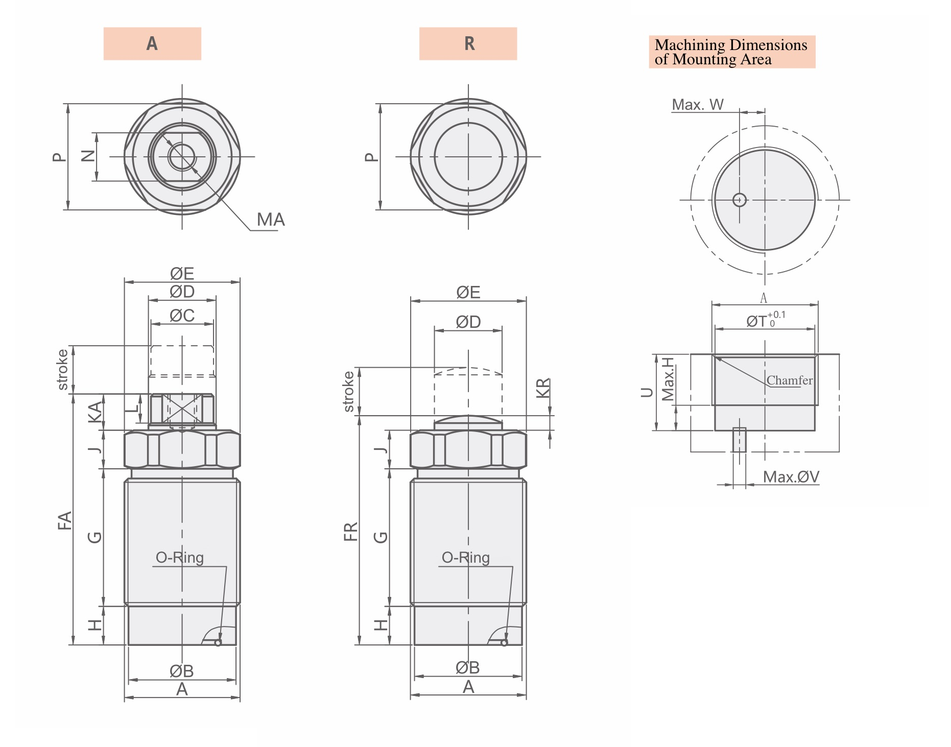
| MODEL | A | B | C | D | E | FA | G | H | J | KA | L | MA | N | P | T | U | V | W | Chamfer | O | ||||||
|---|---|---|---|---|---|---|---|---|---|---|---|---|---|---|---|---|---|---|---|---|---|---|---|---|---|---|
| S | M | L | S | M | L | S | M | L | ||||||||||||||||||
| CTC-K024 | M24×1.5 | 22.3 | 13 | 14 | 24.5 | 39.5 | 47 | 63.5 | 17.5 | 25 | 41.5 | 8 | 7 | 7 | 5.5 | M6×7 | 10 | 22 | 22.5 | 14<U<24 | 14<U<32 | 14<U<48 | 3 | 5.5 | C1 | AS568-017 |
| CTC-K030 | M30×1.5 | 28.3 | 17 | 18 | 30 | 43.5 | 52.5 | 72 | 18 | 27 | 46.5 | 9 | 8 | 8.5 | 7 | M8×10 | 14 | 27 | 28.5 | 15<U<26 | 15<U<35 | 15<U<54 | 6 | 6 | C1 | AS568-020 |
| CTC-K036 | M36×1.5 | 34.3 | 19 | 22.4 | 35.5 | 51 | 64 | 85 | 23.5 | 36.5 | 57.5 | 10 | 8 | 9.5 | 8 | M8×10 | 17 | 32 | 34.5 | 16<U<32 | 16<U<45 | 16<U<66 | 6 | 8 | C1 | AS568-120 |
| CTC-K045 | M45×1.5 | 43.3 | 28 | 30 | 45 | 59 | 72 | 94.5 | 23 | 36 | 58.5 | 12 | 12 | 12 | 10 | M10×11 | 24 | 41 | 43.5 | 18<U<34 | 18<U<47 | 18<U<69 | 8 | 10 | C1 | P31.5 |
| CTC-K055 | M55×2 | 52.6 | 34.5 | 35.5 | 55 | 64 | 79.5 | 102 | 27 | 42.5 | 65 | 12 | 12 | 13 | 11 | M12×12 | 30 | 50 | 53 | 20<U<38 | 30<U<53 | 20<U<76 | 8 | 13 | C1.5 | P39 |
| MODEL | A | B | D | E | FR | G | H | J | KR | P | T | U | V | W | Chamfer | O | ||||||
|---|---|---|---|---|---|---|---|---|---|---|---|---|---|---|---|---|---|---|---|---|---|---|
| S | M | L | S | M | L | S | M | L | ||||||||||||||
| CTC-K024 | M24×1.5 | 22.3 | 14 | 24.5 | 35 | 42.5 | 59 | 17.5 | 25 | 41.5 | 8 | 7 | 2.5 | 22 | 22.5 | 14<U<24 | 14<U<32 | 14<U<48 | 3 | 5.5 | C1 | AS568-017 |
| CTC-K030 | M30×1.5 | 28.3 | 18 | 30 | 38 | 47 | 66.5 | 18 | 27 | 46.5 | 9 | 8 | 3 | 27 | 28.5 | 15<U<26 | 15<U<35 | 15<U<54 | 6 | 6 | C1 | AS568-020 |
| CTC-K036 | M36×1.5 | 34.3 | 22.4 | 35.5 | 45 | 58 | 79 | 23.5 | 36.5 | 57.5 | 10 | 8 | 3.5 | 32 | 34.5 | 16<U<32 | 16<U<45 | 16<U<66 | 6 | 8 | C1 | AS568-120 |
| CTC-K045 | M45×1.5 | 43.3 | 30 | 45 | 51 | 64 | 86.5 | 23 | 36 | 58.5 | 12 | 12 | 4 | 41 | 43.5 | 18<U<34 | 18<U<47 | 18<U<69 | 6 | 10 | C1 | P31.5 |
| CTC-K055 | M55×2 | 52.6 | 35.5 | 55 | 56 | 71.5 | 94 | 27 | 42.5 | 65 | 12 | 12 | 5 | 50 | 53 | 20<U<38 | 30<U<53 | 20<U<76 | 8 | 13 | C1.5 | P39 |